The deeper sleeper machine

This idea has been brought to life
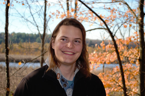
Rob is a biomedical engineering PhD student at the University of Ottawa. He regularly uses the Makerspace as part of his research, and loves designing and building devices to tackle all kinds of problems.
Rob is a biomedical engineering PhD student at the University of Ottawa. He regularly uses the Makerspace as part of his research, and loves designing and building devices to tackle all kinds of problems.
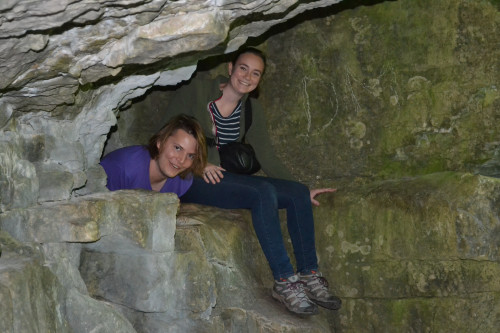
Amelia is a biomedical engineering graduate from the University of Guelph with an interest in wearable devices, crafting, designing and experimenting. she's created things from D&D set pieces to heart monitors!
The Deeper sleeper machine was brought to life by Engineers, Rob Hunter and Amelia French.
They said about the Deeper Sleeper machine...
'This was a great experience but the best part was interacting with the inventor. It's great to see someone so excited about technology! We've designed bio-signal devices in the past, but we still encountered some challenges. The biggest hurdle was soldering everything together, but we are happy with the end result!'
Chanpreet even got a chance to Skype with Rob Hunt to discuss her ideas for the deeper sleeper machine!
Blog entries

Chanpreet was a part of the making process the whole way through. Rob Skyped with her to describe how they intend to make the invention into a real thing and a bit about the technology behind the deeper sleeper machine
It's time to deliver the final deeper sleeper machine! See you soon at the Canadian Space and Aviation Museum!
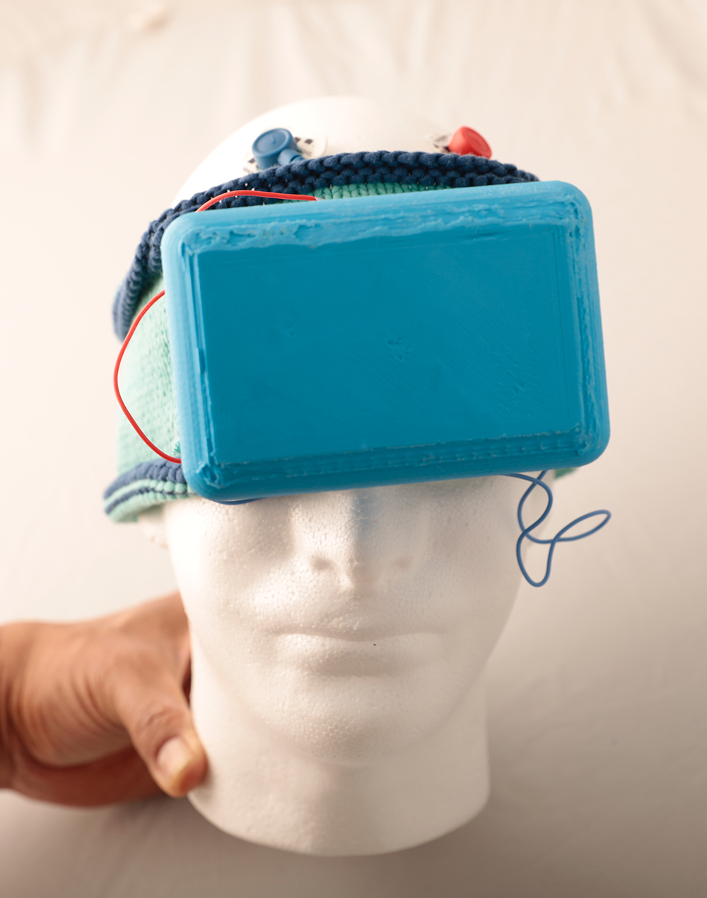
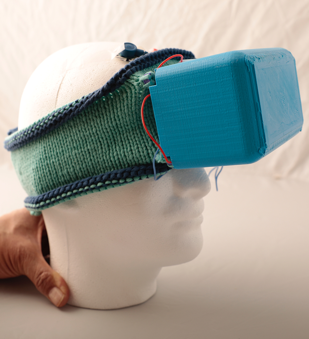
Now that the deeper sleeper machine is all assembled it's time to see how it works. We made an app that connects to the headband via Bluetooth to measure how well you are sleeping. Here are some pictures of Rob wearing the deeper sleeper machine and the app that goes along with it. Also a graph of brain activity that we recorded!
We are using alpha waves (awake brain waves) and delta waves (deep sleep brain waves) to figure out sleep quality. The brain image on the app changes from red (off) to green (awake) to blue (asleep). The circuit box is comically large but this is just the first prototype, so it would be optimized to be much smaller (and more comfortable) for future iterations.
The headband is knitted and the circuit is soldered together, now it's time to assemble! We designed a 3D printed box to house the circuit, batteries, and microcontroller. The box was attached to the headband and the components inserted into the box.
Picture 1: Parts have arrived! Time to start construction of the final circuit.
Picture 2 and 3: First is the “instrumentation amplifier” which takes two signals and subtracts them. The signal from the middle of the brain is just background noise and doesn’t contain much useful information, so if we subtract the signal from one hemisphere from the signal in the middle of the brain we isolate the brain waves!
Picture 4 and 5: Lots more added now! All of the op-amps (the big triangles in the circuit drawing) are all inside the new chip in the middle of the board to save on space. The filters isolate the frequency range of the brain waves, and the conditioning circuit makes the signal compatible with the computer controlling the whole system.
Picture 6: The brains of the operation! This is the microcontroller (a little computer) that runs the show. It has Bluetooth on it so it can talk to your phone.
Picture 7: Final version of the circuit all soldered together and ready to go with the electrodes. The electrodes have a conductive gel on them to get the electricity from your skin.
To start this project we first decided to design the circuit that will be used in the EEG. To do this we need to be able to capture the frequencies that the brain emits. The alpha and delta waves (7-12 Hz and 1-4 Hz respectively) are the main brain waves associated with sleep. In order to capture just this section we need to filter the signal that is received through the electrodes that will be placed on an astronaut's head. We used both a high pass filter, which allows frequencies above a certain amount through, and a low pass filter which allows frequencies below a certain amount through in order to capture the 1-12 Hz range. The pictures that we have included show the first circuit design that was built and the signal that we got from using it!
What our experts think!

What a smart idea! This would be great for use by astronauts, to help them to monitor their sleep by providing them with direct daily feedback, as indeed their sleep on the ISS is disrupted, and they do tend to sleep quite a bit less than on Earth. In addition, they frequently have to sleep-shift in preparation for the arrival of cargo vehicles or other space vehicles coming to dock with the ISS. Sleep-shifting is when they have to completely shift their sleep/wake times, a bit like long-haul travel, which causes “jet-lag”. This further disrupts their sleep, which could cause fatigue and affect alertness levels. The “Deeper Sleeper” could help the astronauts by monitoring their sleep patterns and providing advice on how to best adjust their sleep times so that they get a good night’s rest and feel alert and refreshed the next morning.